
 Simple Homopolar Motor - Guide ready to print or save as a PDF file
Single Homopolar Motor ⚡🧲
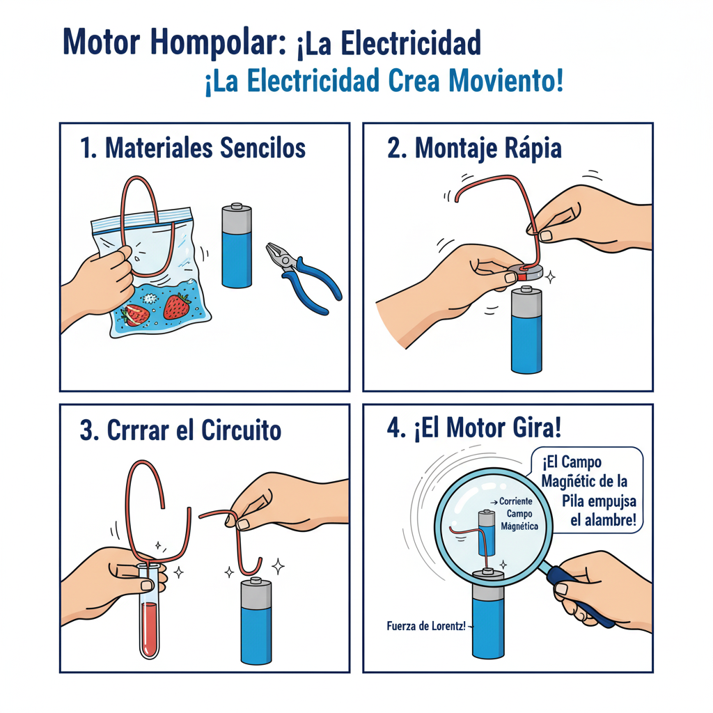
A mini-motor that rotates thanks to magnetic force on moving loads. Quick assembly, instant WOW effect!
Clear and challenging objectives 🎯
- General Objective: Construct and explain the operation of a homopolar motor to rotate visibly and stably for at least 10 seconds.
- Personal objective: Adjust wire shape to improve speed/stability and record changes with data.
Simple and fun theoretical introduction 🌍
A homopolar motor is the simplest electric motor. It uses a battery, a magnet and a wire. When current flows through the wire inside a magnetic field, a Lorentz force that pushes the wire, and it turns!
- ⚡ Electric current: flow of electrons from the negative to the positive pole.
- 🧲 Magnetic field: region around the magnet where the magnetic force acts.
- ✋ Lorentz force (F = q-v × B): deflects moving charges within a magnetic field.
- 🔁 Homopolar: the field is approximately uniform and does not change polarity during rotation.
Applied scientific method 🔬
- Observation: The wire rotates when it touches the battery and the magnet.
- Question: Which wire form produces the greatest stability and speed?
- Hypothesis: If I center the wire and under the friction with a symmetrical loop, then rotation will be more stable and faster.
- Experimental design: Test 3 wire designs (cone, spiral, heart) keeping battery and magnet constant.
- Data collection: Measure continuous rotation time and number of revolutions per 10 s.
- Analysis: Compare averages and variability; choose the best design.
- Conclusion: Confirm or refute the hypothesis with evidence.
- Communication: Present poster with photos, tables and brief explanation of the Lorentz force.
Graphical description of assembly 🧩
This is what the assembled motor looks like: battery in vertical position, magnet attached to the negative pole and a copper wire forming a loop that rubs against the positive pole and the magnet.
   Side view (simplified)

      (+) pole Wire (top contact).
      ┌───┐ ┌───────────────────┐
      │ + │ │ │
      │ │ │ │ │ loop │
      │ │ │ │
      │ - │ └───────┬───────────┘ ← side contact with magnet.
      └───┘ │
       battery 🧲 neodymium magnet (at the negative pole).
BOM with smart options 🛠️
| Material | Economic | Standard | Professional |
|---|---|---|---|
| Battery 1.5 V | AA common (alkaline) | High capacity AA | Type C/D (more mass → greater inertia) |
| Magnet | Neodymium in button (N35) | Neodymium N42 | Neodymium N52 (strong: use with care) |
| Copper wire | Rigid wire 1 mm without varnish | Enameled wire 0.8-1 mm (scrape ends) | Copper OFC 1-1.2 mm (better conductivity) |
| Accessories | Cardboard base, tape | 3D printed support or wood | Acrylic base and battery holder |
| Security | Basic glasses | Glasses + cotton gloves | Anti-impact goggles + insulating gloves |
Step-by-step guide 🧭
-
Prepare the base
Place the battery upright on a stable base. Secure the magnet to the negative pole.
Scientist Alert! Check the polarity of the magnet: the attraction to the negative pole must be strong. -
Shapes the wire
Bend the wire to form a loop that touch gently touch the positive pole and, at the bottom, rub the magnet.
Pro Tip: Creates a centering tip at the top and a hook at the bottom to minimize lateral friction. -
Complete the circuit
Place the wire over the positive pole and lower the bottom of the wire until it touches the magnet. The wire should start to rotate.
Scientist Alert! If it does not rotate, adjust the balance: contact should be gentle but continuous. -
Measure and improve
Record steady spin time and turns in 10 s. Test 2-3 wire designs and compare.
Pro Tip: Clean the contacts (eraser or fine sandpaper) to reduce resistance. -
Security and locking
Interrupt contact after each test to prevent the battery from overheating.
Danger Zone: Do not leave the motor running unattended. Keep magnets away from pacemakers and devices.
Prepare your presentation for the trade show 🎪
- Poster: Large title, assembly photos, simple diagram and Lorentz formula.
- Demonstration: Show 2 wireframe designs and explain why one rotates better.
- Phrases for judges: “My independent variable is the wire shape and measured laps/10 s as a dependent variable”.
- Interactivity: Offers the audience to try a twist (with supervision and gloves).
Useful appendices 📎
Data logging template
| # Test | Wire shape | Laps in 10 s | Stable turning time (s) | Remarks |
|---|---|---|---|---|
| 1 | Cone | |||
| 2 | Spiral | |||
| 3 | Heart |
Checklist
- ✔ Battery with good charge
- ✔ Well centered and firm magnet
- ✔ Clean contacts and balanced wire.
- ✔ Timer and notebook at the ready
- ✔ Glasses and gloves available.
Recommended sources
- Popular books on electromagnetism (high school level).
- Educational physics sites with home experiments and electrical safety.
- Biographies of Michael Faraday and resources on the Lorentz force.